Valve Adjustment Procedure
Our customers often ask us to explain the correct procedure for adjusting the valve lash on their engines. We’re often told that the service manuals, instructions included with their camshafts, or the advice from others is often confusing or varies substantially between each source. Such variations of the techniques or procedures to perform this engine maintenance task should not exist. The information and step-by-step procedure provided below should make it easy for just about everyone reading this article to understand—from the professional technician, engine builder or racer, to the home mechanic / do-it-yourselfer (DIY) attempting this task for the very first time.
Introduction to Adjusting Solid and Hydraulic Lifters
- Does the engine use steel (cast iron) or aluminum cylinder heads?
- Are the correct valvetrain components installed on the application? (Proper valve stem and pushrod length, correct lifters, correct rocker arms and retention)
- Are ALL of the valvetrain components in proper working condition?
- Are the valve springs the correct size and tension for the camshaft and intended use (operating RPM)?
- What type of driving (or racing) will this engine experience? (Daily driver, street/strip, racing, type of racing)
- Are the proper tools available, and do we possess the basic knowledge required to perform this task?
The last one above is quite important. If after reading through this information and you find that you are still a bit confused, please ask for help or have someone else do it. In the very least you can have someone who is more knowledgeable walk you through the process we describe here to make sure you understand the procedure. If you are wondering what can go wrong, here is a short list that describes a few troubling results.
- Poor running engine and low performance
- Failed smog test (if this is an emission-controlled, street driven vehicle)
- Burnt exhaust valve(s)
- Broken valvetrain components (springs, pushrods, lifters, camshaft)
- Limited or reduced lifespan of valvetrain components
- Excessive valve guide and valve seat wear
- Blown up engine
- Lose an important Race!
- Empty, or put a substantial dent in your bank account
The above list, though quite simple to understand, should scare us! It takes only a few thousandths of an inch (0.001″) of adjustment error to cause any one or more of the problems listed above.
IMPORTANT WARNING:
Please Note
This article was written somewhat backwards, and there is a very good reason for doing so. It is important that the reader of this article is exposed to the procedure and then describe how it works and why it works. Experience has shown that although the reader was asked to forget what was learned in the past regarding this procedure, such grand requests rarely occur. For some, the whole experience of adjusting an engine’s valvetrain is confusing enough. Trying to erase embedded knowledge is often something that sounds good but is out of reach, and not a rational request.
To compensate for this, while understanding how people think and retain information, the reader will be exposed to the procedure first. This will hopefully generate a bit of thought and understanding that is clarified later in the article.
Please read through ENTIRE article before attempting to adjust the valve lash on the engine!

Understanding "Opposites"
To begin, it is important to understand what is meant by “opposites” in the engine’s firing order. All engines have a specific firing order, or the sequence in which the compressed air and fuel mixture for each cylinder is ignited by the ignition system. The design of the engine determines the firing order and is directly related to the engine crankshaft and camshaft. Both help determine the firing order—when the piston is at the top of the cylinder (TDC), or when each valve is closed or opened, and therefore, when the ignition system ignites the spark plug.
What does “Opposite” mean?
adjective
– situated, placed, or lying face to face with something else or each other, or in corresponding positions with relation to an intervening line, space, or thing:
– being the other of two related or corresponding things’
For our explanation we are looking for those cylinders that are opposite in the engine’s firing order. This is not opposite sides of the block, or odd versus even numbers. It is ONLY related to the engine firing order.
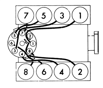
Examine this graphic, showing a common GM V8 engine with the 1-8-4-3-6-5-7-2 firing order. The front of the engine is to the right, and the ignition distributor sits at the rear of the engine behind the #7 and #8 cylinders.
The graphic shows that the odd-numbered cylinders rest on the left (common driver side) of the engine) top of the graphic), and the even-numbered cylinders rest on the right side (common passenger side) of the engine.
On the distributor cap, we can also see that the plug wires (lines connecting the cylinders to locations on the distributor cap) are not in numeric sequence (1-2-3-4-5-6-7-8). There is an arrow just off of center on the distributor cap that designates rotor rotation of clockwise. Beginning with the #1 location on the distributor cap (facing toward the front of the engine in this graphic), and following the rotation arrow, the firing order is clearly provided.
1-8-4-3-6-5-7-2
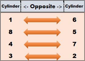
The firing order can now be cut in half, showing the OPPOSITES of the firing order. Take the first four numbers in the firing sequence and place them against the second four numbers in the sequence. We now have (1-8-4-3) and (6-5-7-2).
To understand more clearly, review the next graphic, where the numbers are positioned vertically. The first four numbers in the firing sequence are provided in the left column, and the second four numbers are positioned in the far right column. Using this firing order, the #1 cylinder is opposite the #6 cylinder, and vice- versa (#6 is opposite #1). #8 is opposite #5, #4 is opposite #7, and #3 is opposite #2.
Again, the firing order is required, and this ONLY works on V-type engines. For other engines, here are some common firing orders and their opposites. PLEASE VERIFY the engine’s firing order. Do not rely on the list below.
| Engine | Firing Order | Opposites |
|---|---|---|
| AMC (most) V8 | 1-8-4-3-6-5-7-2 | Same as example above |
| Buick V8 (most) | 1-8-4-3-6-5-7-2 | Same as example above |
| Chrysler Big Block & Hemi V8 | 1-8-4-3-6-5-7-2 | Same as example above |
| Chrysler Small Block V8 | 1-8-4-3-6-5-7-2 | Same as example above |
| Oldsmobile (1967-later) V8 | 1-8-4-3-6-5-7-2 | Same as example above |
| Pontiac (1955-1981) V8 | 1-8-4-3-6-5-7-2 | Same as example above |
| Ford 5.0L HO, 351W, 351C, 351M, 400 V8 | 1-3-7-2-6-5-4-8 | 1 & 6; 3 & 5; 7 & 4; 2 & 8 |
| Ford (most other) V8 | 1-5-4-2-6-3-7-8 | 1 & 6; 3 & 5; 7 & 4; 2 & 8 |
Engine OFF Valve Adjustment Procedure
First, review the description below showing Small and Big Block Chevy, and other engines using the 1-8-4-3-6-5-7-2 firing order. is it easy to understand?A more detailed explanation follows below the chart. For other engines, use the firing order that matches the engine to create a similar chart.
Intake Valve Adjustment: ENGINE OFF!
-
-
- with #1 cylinder Intake Valve at full valve lift …. Adjust #6 Intake Valve
- with #8 cylinder Intake Valve at full valve lift …. Adjust #5 Intake Valve
- with #4 cylinder Intake Valve at full valve lift …. Adjust #7 Intake Valve
- with #3 cylinder Intake Valve at full valve lift …. Adjust #2 Intake Valve
- with #6 cylinder Intake Valve at full valve lift …. Adjust #1 Intake Valve
- with #5 cylinder Intake Valve at full valve lift …. Adjust #8 Intake Valve
- with #7 cylinder Intake Valve at full valve lift …. Adjust #4 Intake Valve
- with #2 cylinder Intake Valve at full valve lift …. Adjust #3 Intake Valve
-
Exhaust Valve Adjustment: ENGINE OFF!
-
-
- with #1 cylinder Exhaust Valve at full valve lift …. Adjust #6 Exhaust Valve
- with #8 cylinder Exhaust Valve at full valve lift …. Adjust #5 Exhaust Valve
- with #4 cylinder Exhaust Valve at full valve lift …. Adjust #7 Exhaust Valve
- with #3 cylinder Exhaust Valve at full valve lift …. Adjust #2 Exhaust Valve
- with #6 cylinder Exhaust Valve at full valve lift …. Adjust #1 Exhaust Valve
- with #5 cylinder Exhaust Valve at full valve lift …. Adjust #8 Exhaust Valve
- with #7 cylinder Exhaust Valve at full valve lift …. Adjust #4 Exhaust Valve
- with #2 cylinder Exhaust Valve at full valve lift …. Adjust #3 Exhaust Valve
-
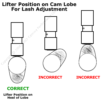
In the instructions above, adjustments are being made on the “opposite” valves in the firing order, specified by the engine rotation cycle. The example shows an engine with the firing order of 1-8-4-3-6-5-7-2. It is these opposites that position the opposing valve at the correct location for adjustment. That proper location is when the lifter resides on the back side (base circle, or heel) of the cam lobe (see previous image), meaning that the valve is in the fully closed position.
Please, DO NOT try to adjust both intake and exhaust valves at the same time. It is NOT accurate, and gets back to the original request of forgetting (or ignoring) what was previously known about valve adjustment procedures. Each valve is adjusted independently. That means specifically, that sixteen (16) individual adjustments will occur on a typical V8 engine.
Explanation of Terms
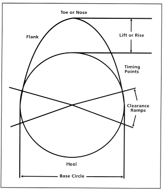
- Full Lift – The valve is OPEN and the lifter is positioned on the nose (highest point) of the cam lobe.
- TDC – Top Dead Center, or where the piston is at the top of the cylinder and both (all) valves for that cylinder are closed.
- Lash – The clearance (cooling time) between the tip of the valve stem and the rocker arm.
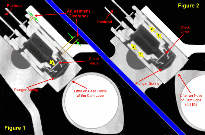
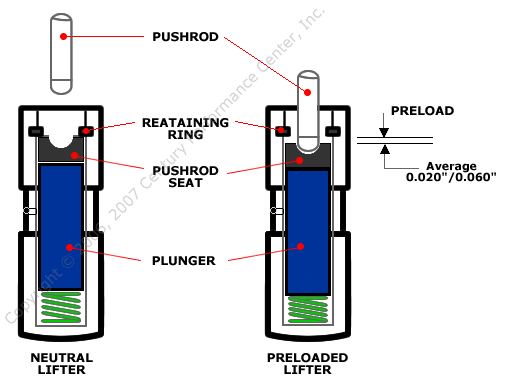
- Zero Lash – No clearance, where the rocker arm is snug to the lifter. On a hydraulic lifer, the plunger is in the uppermost neutral position (not compressed)
- Camshaft Lobe Base Circle – Includes the ‘heel’ or bottom of the cam lobe. When the lifter is on the base circle of the cam lobe, the valve it controls is closed.
- Camshaft Lobe Toe or Nose – The highest point of the cam lobe opposite the base circle, and where the valve is at its highest point (greatest opening, or full lift).
- Camshaft Lobe Ramp – (also known as ‘lift’ or ‘rise’ on the valve opening side of the lobe, and ‘flank’ on the closing side.
Importance of Lifter Position
If the position of the lifter on the camshaft lobe is anywhere other than on the heel (reference the adjacent graphic) where there is NO ramp contact when making adjustments, the lash setting will be incorrect. Proper position of the lifter on the cam lobe is required for each valve before attempting to perform adjustment. The chart and procedure above ensures that the lifter is on the backside of the cam lobe for each valve.
In the past, service manuals and our auto shop teachers instructed us to position each piston an at TDC for that cylinder (piston at Top Dead Center), and then adjust both valves for that cylinder. However, we often find that this is not the correct procedure to obtain a proper valve lash setting, especially on modern engines or those with aggressive camshaft profiles. The image shows the required position of the cam lobe relationship to the lifter to ensure the foundation for performing the correct valve lash adjustment.
What About the Actual Adjustment Procedure?
Hydraulic Lifter Camshafts
Engine "OFF" Hydraulic Lifter Adjustment Tips:
If the engine is complete and installed in the vehicle, warm up the engine by running it until it gets to operating temperature (15-minutes or so). “Cold” adjustments should only be used on new engines as a preliminary adjustment on the engine stand. Once a new engine has been started and the initial break-in procedures complete, re-adjusting the valves “hot” is recommended.
- Have all necessary tools ready and then quickly remove the valve cover(s) after the engine has achieved operating temperature.
- Begin the adjustment procedure by using the chart provided above in this article, or one to match your engine firing order and document the opposites.
- With the #1 Intake valve at FULL LIFT — This means turning the engine by hand until the intake valve on the #1 cylinder is fully open (watch the rocker arm push down on the top of the valve stem, compressing the valve spring until it stops moving downward) — and adjust the intake valve on “opposite in firing order” cylinder. Always remember, adjustment occurs on the opposite valve based on the engine’s firing order.
- Go to the opposite cylinder. This technical article uses the common firing order for small and big block Chevy engines as the example, so this would be the #6 cylinder.
- Loosen the rocker nut (if using roller rockers there is typically a Jam Nut that requires loosening with an Allen wrench) on the #6 intake valve.
- Take two fingers and spin the pushrod back and forth between them to feel for resistance.
- Carefully snug the adjustment nut and STOP when resistance is felt on the pushrod as it applies pressure to the seat of the rocker arm and lifter, this is considered “zero lash.”
- Turn the wrench 1/8 to 1/4 turn (see below) for performance, racing, or high RPM applications. Turn the wrench 1/4 to 1/2 turn for stock or mild street applications. For applications that regularly operate at consistent high RPM, use the slightly lighter setting of (1/8 turn).
- If this valvetrain uses poly-locks, remember to reset (snug) the Allen screw
- The adjustment for this valve is now complete!
- Turn the engine by hand SLOWLY to the next cylinder / valve in the firing order, again finding full lift of the next valve.
- Repeat the above steps, starting at #3 through #10, but use the next cylinder in the sequence. In our Chevy V8 example this is the intake valve for the #8 cylinder
- Continue through all the intake valves and then start the procedure over for the exhaust valves.
What Describes 1/4 Turn? (see image below)
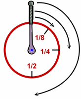
TIP: One way to tell if a lifter is bleeding off or not retaining oil consists of watching the rocker arm while applying the 1/8 to 1/2 turn of the wrench. If the rocker pushes the valve stem down instead of the pushrod, the vale is opening instead of adjusting the lifter!
Engine RUNNING Hydraulic Lifter Adjustment
- Adjust only one side of the engine at a time.
- Use oil restrictors (deflectors) on the rocker arms, or better yet a butchered up old valve cover that has an access cut into the top of it to facilitate adjustment access AND oil deflectors
- Stay calm … getting burnt a bit is common. Messes can occur no matter how careful. If not adjusting the valves properly the first time through, it doesn’t get easier or become less of a frustration.
- Using a mechanic’s stethoscope can make this task substantially easier, especially if the engine is loud or we have hearing issues.
Adjusting hydraulic lifters with the engine running is not one of my favorite activities. With the above considerations addressed we are ready to get started:
- Start the engine and allow it to warm up.
- Turn off the engine
- Remove one valve cover and install the deflector clips, custom valve cover, or whatever apparatus available to keep oil splash to a minimum.
- Start the engine back up.
- Begin to loosen one of the rocker arm adjusting nuts. The valvetrain will begin to gently “clatter” like an old sewing machine.
- Slowly tighten the rocker nut down, just until the louder volume of “clatter” reduces.
- Turn the wrench an additional 1/8 – 1/2 turn to set the plunger depth to the proper lifter preload. (see information above)
- Continue (repeat) this procedure on each of the remaining the valves.
- Turn off the engine
- Remove the oil splash prevention apparatus and re-install the valve cover.
- Repeat these steps on the other engine bank (if a V-type engine).
Solid Lifter Adjustment
Compensating for a Cold Engine When Adjusting the Valve Lash
- Using iron block and iron heads, add .002″
- Using iron block and aluminum heads, subtract .006″
- Using both aluminum block and heads, subtract .012″
Using Valve Lash to "Tune" Engine Performance
-
- Reducing the lash will increase top end (upper RPM power) horsepower
- Increasing the lash can improve low end torque and acceleration
Closing Remarks & Tips
- As mentioned above, the power band can change slightly on an engine using a solid lifter camshaft by varying valve lash settings. A looser lash setting increases the low-end power of the engine where a tighter lash increases top-end power. Careful consideration is necessary for these tweaks because the valve lash is the “Cooling Time” that the valve needs on each reciprocal cycle. If the engine has too little, or no lash, damage to the valves is possible.
- Using roller rocker arms dramatically increases valve guide life, increases horsepower and is also better at maintaining valve lash settings. Use them whenever you can! Shaft style rockers are best (less deflection). Stainless steel rockers provide less “over the valve weight”, which is GOOD. Aluminum, though less expensive will deflect more and increase the actual weight over the valve stem, but are still better than stamped steel or OE-style rocker arms. The added weight may not seem critical, but this is considered reciprocal weight, which slows down all the components related to it.
- Additionally, a valve lash setting that is too loose can damage the valve stem and increase the possibility of premature failure of the roller rocker tips. If using OEM style, stamped steel rocker arms, fracturing of the rocker arm or galling at the fulcrum is possible.
- Engine materials, engine operating RPM, and valvetrain deflection contribute to varying valve lash settings. The higher the RPM, the cheaper the parts in use, and the performance and reliability differences between types of materials contribute to more frequent valve lash adjustments. (By the way, while the valve covers are off, make the effort to test the valve spring pressures. There are tools available for installed testing of spring pressures).
- There is FREE horsepower when using a Roller Camshaft. If within the budget, use a roller cam! Plus, when using a roller cam, camshafts changes can occur without the need to change lifters or endure those annoying, yet extremely important, camshaft and lifter break-in procedures. This process is mandatory with Hydraulic or Solid “tappet” camshafts.
Have questions regarding this information?
Or, call our dedicated support staff at (775) 746-4887
Please review other helpful tech articles
