Fuelish Tendencies
A play on words that combines ‘fuel’ and ‘foolish’. Fuel, because this article discusses automotive and marine fuel system design and components. Foolish, because mistakes in fuel system design can result in lost races, personal injury, damaged components, or destroyed engines. The tendencies for this type of problem is more common that many may realize.
Some Basic and Fundamental Information:

However, if a pump rated at 33 GPH on a 400 HP engine or a 400 HP nitrous system was installed on this application using the above example, the engine would experience severe fuel starvation and someone’s wallet would cringe in pain as it quickly empties when replacing various parts or an entire engine! Ouch, and why could this occur?
There are several reasons why relying on this calculation will destroy an engine. However, the main reason is related to how fuel pumps are rated. Fuel pumps are typically rated at “zero” pressure (also known as “free flow”). Rating a fuel pump at zero pressure is useless and nothing more than a marketing gimmick, because the pump will never operate at zero pressure when it is supplying fuel to the engine. As fuel pressure increases, the fuel pump slows down and fuel output is reduced. If using a standard “dead-head” type regulator, the pump on a common carbureted application may be forced to produce as little as 25 PSI. At 25 PSI the actual output GPH of the pump is much less than its “free flow” rating.

Choosing the Correct Size Fuel Pump
Multiply maximum horsepower by 0.23 to calculate minimum pump size in “free flow” GPH.
Example: 400 HP x .23 = 91 GPH “free flow” or lowest possible fuel volume requirement.
For Return-Style regulators:
Example: 400 HP x .17 = 68 GPH “free flow” or lowest possible fuel volume requirement.
- Up to 250 HP = 5/16″ or -04 AN
- Up to 375 HP = 3/8″ or -06 AN
- Up to 700 HP = 1/2″ or -08 AN
- Up to 1000 HP = 5/8″ or -10 AN
- Up to 1500 HP = 3/4″ or -12 AN
If using a return-style regulator, an adequately sized return line from the regulator back to the tank is also required. The size of the return line is dependent on the size of the pump you are using, regardless of the engine’s horsepower output. The return line must operate at a measured limited (below supply) or preferred ZERO pressure. In most cases, the minimum return line size matches that of the supply line, but a larger return line is often preferred.
- Up to 45 GPH = 5/16″ or -04 AN
- Up to 90 GPH = 3/8″ or -06 AN
- Up to 250 GPH = 1/2″ or -08 AN
- Up to 450 GPH = 5/8″ or -10 AN
Mounting the fuel pump also takes some thought and planning. The fuel pump must be mounted as low as possible and as close to the fuel cell (or tank) as possible. DO NOT mount the pump above the fuel tank. However, the type of fuel pump needs to be taken into account here. Gerotor style pumps provide little to no initial suction, and are push-only style pumps. Mounting a gerotor pump at a location that does not provide gravity-fed fuel delivery will cause the pump to burn up and fail in short order. Vane style pumps do offer a limited amount of suction. However, the more suction, the less efficient the design of the pump. Follow the pump manufacturer’s installation instructions on mounting location, but keep the above facts in mind when planning the most effective and safe mounting location.
Mount the fuel pressure regulator as close to the engine as possible. (Note: There are some specific exceptions to this rule. Please review the system designs below.) DO NOT use restrictive fittings, especially sharp 90º or “T” fittings. If the only option is a 90º or “T” fitting, use tube style AN (Army-Navy) fittings from Earl’s, Russell, Goodridge, or other quality brands.
Good and BAD Plumbing Fitting Designs
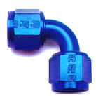
Of course the fitting at left is what we want to use for optimum flow and minimal restriction. The inherent restriction of the fittings at right can be hazardous to our race engines and affect the consistent ability to win races. The first image is an example of a typical full-flow AN fuel fitting, while the second image show very restrictive brass fittings.
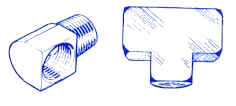
The restrictions caused by improper components or plumbing of a fuel system can cause adverse and costly consequences. It was decades ago when race teams copied technology from the aerospace industry (as they tend to do regularly) in using stainless steel braided fuel lines and AN (Army Navy) fittings, including full-flow screw together hose ends and adapters that drastically reduced common fluid restrictions. Removing fuel flow restrictions and turbulence provided the benefit of using smaller, lighter, and more efficient fuel pumps. Engines were able to make more horsepower throughout the RPM range, were more consistent, and lasted longer. The braided lines resisted wear, heat, and compression, and the hose ends reduced turbulence and restriction while providing added safety, and easier installation and removal. AN hose ends and adapters are manufactured to provide complex bends and connection angles that were previously a plumbing nightmare.
Fuel Pressure Regulators and Benefits of the Return-Style System

Why a Return-Style Regulator is Recommended
Why does an engine builder, tuner, fuel pump manufacturer, carburetor builder, or this author recommend or mandate using a return-style fuel pressure regulator for the majority of vehicles? A few easy-to-understand reasons come to mind:
- To avoid problematic headaches (such as fuel pump failure just before a final-round elimination, and not having enough time on a hot-lap, or for that matter having a spare pump, to fix the problem in time for the next race. Loss By Default because the dead-head regulator helped shorten the life expectancy of the fuel pump.
- The bypass in the pump is plugged or disabled when running a return-style regulator so there is no chance of that component failing.
- The pressure just before and after the pump is always the same on a return-style system. Utilizing multiple pressure gauges is not required. Fewer components and issues to monitor.
- The return regulator has complete control over the pump pressure and will automatically compensate for pressure drop in the fuel line.

Fuel Pressure Adjustments
Fuel System Designs
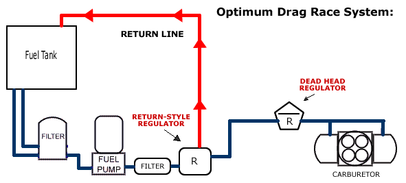
BEST Drag Race System — (return style regulator, plus a dead head regulator … weight savings, and efficiency)
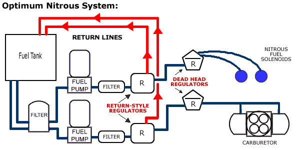
BEST Drag Race Nitrous System — (two independent systems, return regulator at pump, one dead head regulator for solenoids, one for carburetor)
BEST Street/Strip System — (two independent systems if using nitrous; return regulators preferred)
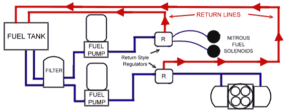
An OK System — (one large system with two dead-head regulators in parallel)

POOR System — (one large system with two regulators in series “not recommended”).

In Closing
A properly designed fuel system offers benefits that help win races, reduce engine damage, and increase vehicle safety. Although safety benefits were not discussed above, be certain that each fuel system component is durable, free from defects, and installed correctly. Mismatched components, poor quality line, hose, or fittings, improper mounting, routing or retention, and other issues can cause costly failures or serious injury.
Return-style regulator systems should be used in all but those applications where class rules prevent it. This is also true for electric versus mechanical style fuel pumps. Electric unless the class mandates something else. Mechanical pumps steal horsepower. Proper sizing of the system (pump volume, line size, etc.) is also extremely important. Do it right the first time to save grief and added expense.
The above graphics only offer a few common fuel system examples. Specific racing systems will vary slightly.
Have questions regarding this information?
Or, call our dedicated support staff at (775) 746-4887
Please review our other articles on fuel systems and other topics.
